
ULF Series
ULF uses its own catalog geometry and load tables. Flanged mounting requires flange and bolt-pattern checks. UVT and ULT are not interchangeable merely because shaft diameters match.
Structure & Application Boundaries
ULF uses its own catalog geometry and load tables. Flanged mounting requires flange and bolt-pattern checks. UVT and ULT are not interchangeable merely because shaft diameters match.
Selection Inputs
Shaft and housing envelope, nut retention / flange dimensions, shaft length, travel, radial load and load direction, torque, speed, duty cycle, accuracy, preload and lubricant/environment.
Product & Configuration
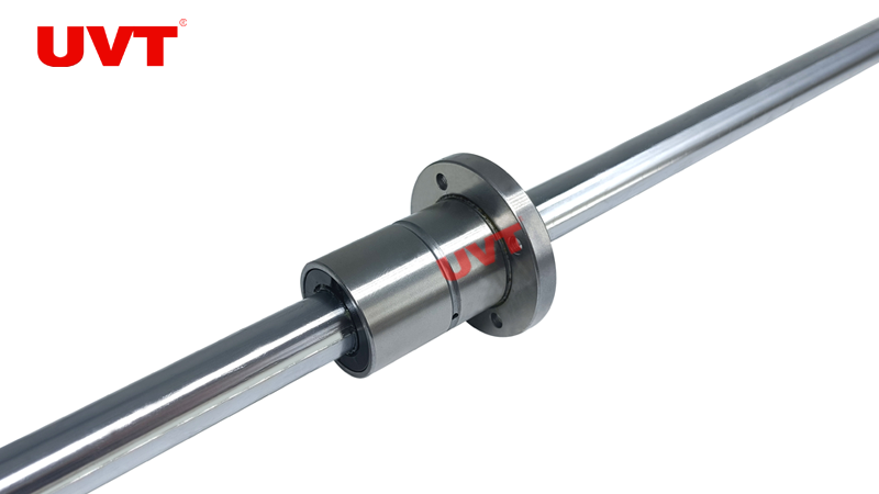
Reference product photo. Files apply only to their named configurations.
Catalog Models
| Model | Shaft d / OD D (mm) | C (N) | C₀ (N) | Details |
|---|---|---|---|---|
| ULF 6 | 6 / 14 | 1220 | 2280 | View model → |
| ULF 8 | 8 / 16 | 1450 | 2870 | View model → |
| ULF 10 | 10 / 21 | 2670 | 4890 | View model → |
| ULF 13 | 13 / 24 | 2730 | On request | View model → |
| ULF 16 | 16 / 31 | 6120 | 11200 | View model → |
| ULF 20 | 20 / 35 | 8900 | 16300 | View model → |
| ULF 25 | 25 / 42 | 12800 | 23200 | View model → |
| ULF 30 | 30 / 47 | 18600 | 23400 | View model → |
| ULF 40 | 40 / 64 | 30800 | 37500 | View model → |
| ULF 50 | 50 / 80 | 40300 | 64900 | View model → |
| ULF 60 | 60 / 90 | 47700 | 79500 | View model → |
Data source: UVT Catalog 2024. Confirm mounting geometry, accuracy and preload against the exact drawing before ordering.
Selection Guides & CAD Requests
ULF10C1R150
Request Configuration Drawing →Guides are general reference PDFs. Request 2D / 3D CAD for your exact configuration.
Complete Model Code
Select series and size; L long nut or A hollow shaft only where offered; C nut count; R shaft length; T0 clearance, unmarked standard or T1 light preload; accuracy and S1/S2 mating identification. Confirm available suffixes against this series drawing.
Mounting & Lubrication
Verify housing or flange dimensions, axial retention and alignment using the exact drawing. Avoid removing the nut without a dummy shaft; confirm lubricant and interval for the application.
Special materials, cleanroom, vacuum and dry-running suitability require individual review.
Related Equipment
- SMT pick-and-place heads
- Semiconductor die bonders
- Micro-assembly robots
- Lab automation