
Where UVT Ball Splines Work
Equipment motion, mounting positions and engineering limitations for four OEM applications.
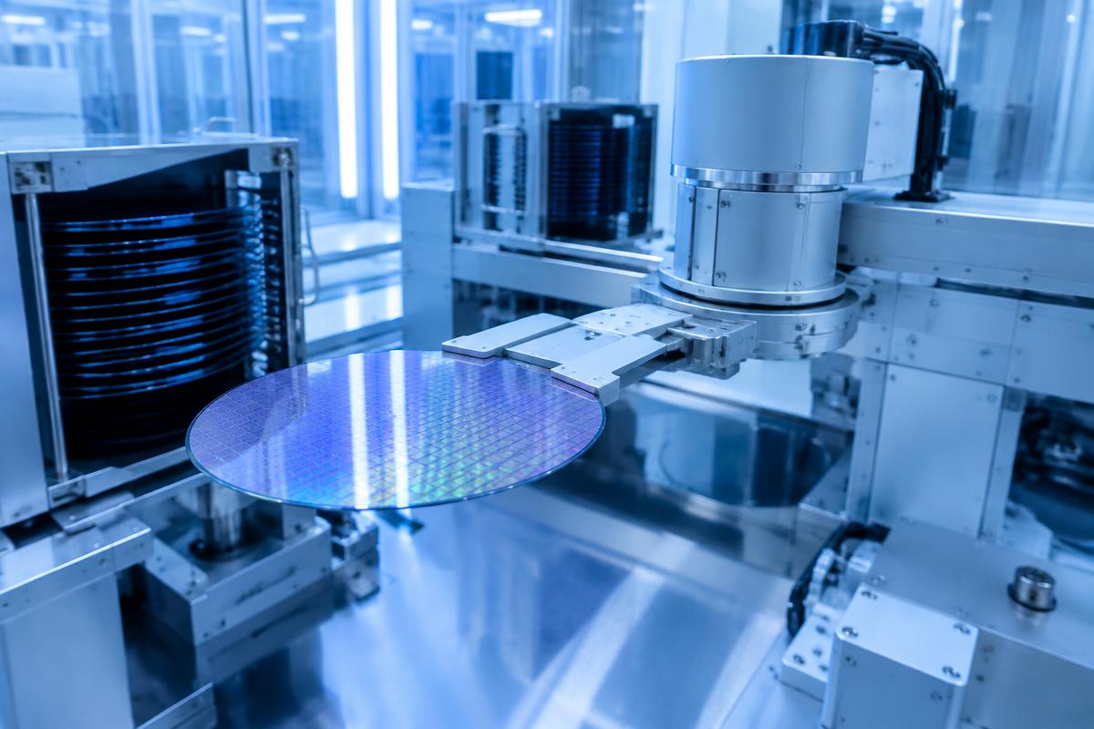

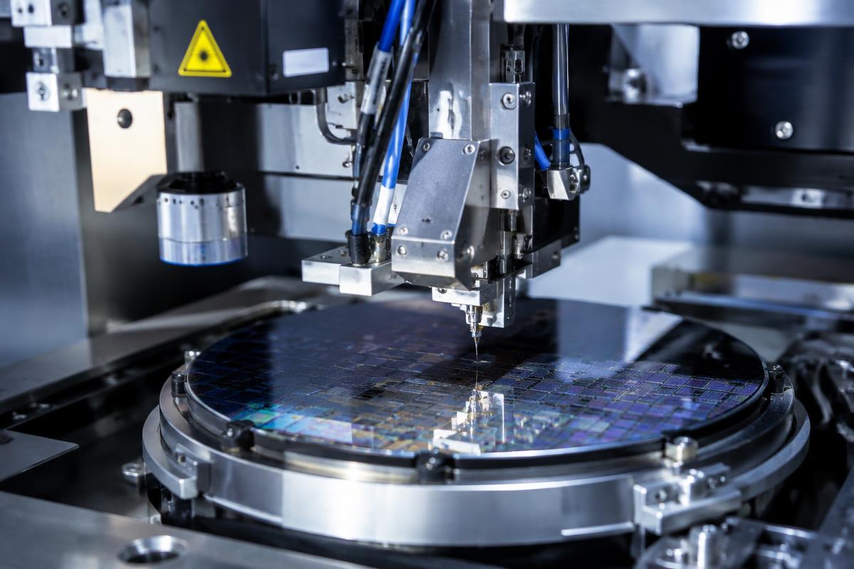
Semiconductor Equipment
Compact die handling demands stable torque transfer and controlled axial motion. Particle generation, accuracy and lubrication must be assessed for the process.
- UVT / UVTF compact series
- Fit, preload and stroke review
- Cleanliness qualification required
- Equipment Principle
- A placement or test axis translates a tool while preserving its angular orientation.
- Spline Installation Position
- Tool spindle or compact transfer axis, supported by the machine bearing and drive system.
- Engineering Limitations
- Small shaft size does not establish cleanroom suitability. Confirm particles, lubricant, vacuum, temperature and contamination protection.
Recommended: Ball Splines
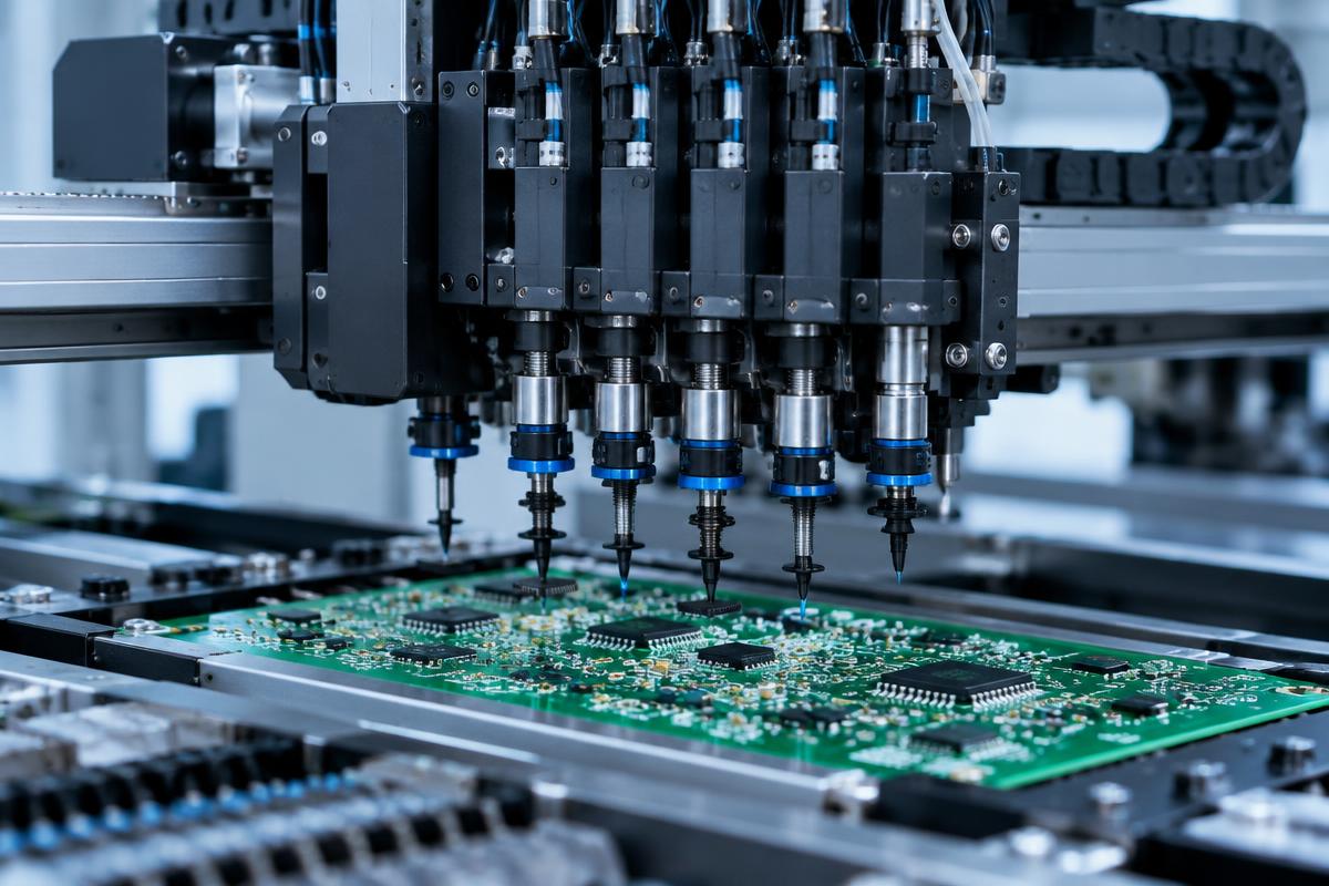
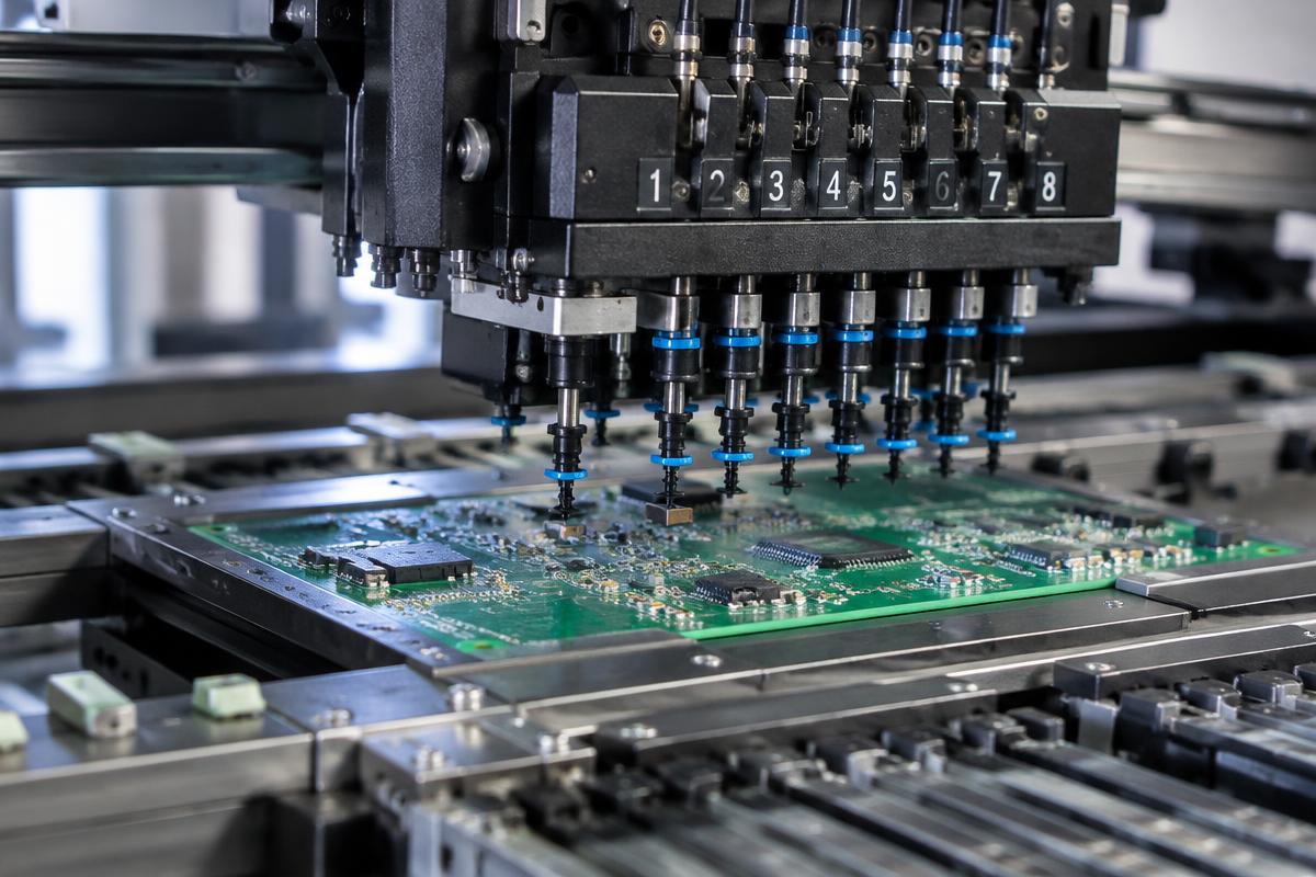

SMT & Pick-and-Place
Repeated nozzle lift and rotation introduce acceleration, torque and wear demands that require a complete duty-cycle assessment.
- UVT / UVTF series
- Placement head integration
- Duty-cycle and lubrication review
- Equipment Principle
- A nozzle axis combines axial travel with torque transmission during pick-and-place.
- Spline Installation Position
- Nozzle Z/θ spindle or a drawing-based multi-axis head assembly.
- Engineering Limitations
- Catalog tests at 860 mm/s, 10G and 15 mm stroke are selected internally verified tests, not a universal speed or life guarantee. Confirm load and maintenance.
Recommended: Integrated Motion Modules

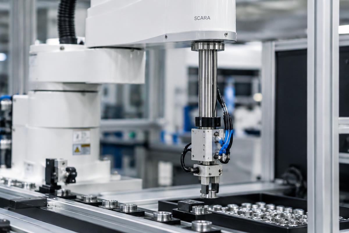

SCARA Robots
The Z–θ axis combines lift and rotation in one shaft; mounting, drive coordination and support-bearing loads are critical.
- UBNS / UNS 16, 20, 25 mm references
- Separate screw and spline ratings
- Support-bearing verification
- Equipment Principle
- The screw interface converts drive rotation into lift; the spline interface transmits torque for tool orientation. Coordinated drives establish Z and θ motion.
- Spline Installation Position
- Vertical tool axis between the two drive nuts, support bearings and end effector.
- Engineering Limitations
- Verify screw lead, nut spacing, axial/radial loads, support stiffness, speed and lubrication separately. Submit the complete axis drawing.
Recommended: Ball Screw Splines



Medical Devices
Analyzers and pipetting mechanisms require controlled motion in a compact envelope, plus application-specific contamination and material review.
- UVT compact series / US limited stroke
- Material and lubricant confirmation
- Equipment qualification by OEM
- Equipment Principle
- Small dispensing or transfer axes guide axial travel while constraining rotation.
- Spline Installation Position
- Pipetting or sample transfer axis, isolated from fluids and cleaning processes as required.
- Engineering Limitations
- No medical-device, sterilization or corrosion certification is implied. US uses effective stroke and needs lubrication; /S catalog options have limited model scope and reduced ratings.
Recommended: Ball Splines
Looking for a replacement?
Send the original model and drawing for dimensional and performance evaluation. Engineering review precedes replacement approval.